

What Seven-layer Model Is Often Used To Describe Networking Technologies And Services?

This article explains the Open up Systems Interconnection (OSI) model and the 7 layers of networking, in plain English.
The OSI model is a conceptual framework that is used to draw how a network functions. In manifestly English, the OSI model helped standardize the manner computer systems send information to each other.
Learning networking is a bit like learning a language - in that location are lots of standards and and so some exceptions. Therefore, it'southward important to really understand that the OSI model is non a set of rules. It is a tool for agreement how networks function.
Once you acquire the OSI model, you will be able to further empathise and capeesh this glorious entity we call the Internet, as well as exist able to troubleshoot networking bug with greater fluency and ease.
All hail the Internet!
Prerequisites
You don't need any prior programming or networking feel to understand this article. However, you will need:
- Basic familiarity with mutual networking terms (explained below)
- A curiosity about how things work :)
Learning Objectives
Over the course of this article, you volition acquire:
- What the OSI model is
- The purpose of each of the vii layers
- The bug that can happen at each of the 7 layers
- The divergence between TCP/IP model and the OSI model
Common Networking Terms
Here are some common networking terms that you lot should be familiar with to become the most out of this article. I'll utilize these terms when I talk most OSI layers adjacent.
Nodes
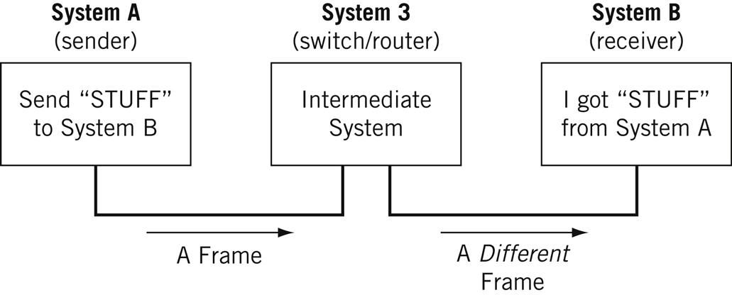
A node is a physical electronic device hooked upward to a network, for example a figurer, printer, router, and so on. If ready properly, a node is capable of sending and/or receiving information over a network.
Nodes may be set upwardly adjacent to one other, wherein Node A can connect directly to Node B, or there may be an intermediate node, like a switch or a router, set up betwixt Node A and Node B.
Typically, routers connect networks to the Internet and switches operate within a network to facilitate intra-network communication. Larn more about hub vs. switch vs. router.
Here's an example:
For the nitpicky among us (yeah, I see you), host is another term that y'all volition encounter in networking. I volition define a host as a blazon of node that requires an IP address. All hosts are nodes, but not all nodes are hosts. Please Tweet angrily at me if you disagree.
Links
Links connect nodes on a network. Links can exist wired, similar Ethernet, or cablevision-free, like WiFi.
Links to can either be betoken-to-point, where Node A is connected to Node B, or multipoint, where Node A is connected to Node B and Node C.
When we're talking about information beingness transmitted, this may also be described as a one-to-ane vs. a one-to-many relationship.
Protocol
A protocol is a mutually agreed upon set of rules that allows ii nodes on a network to substitution information.
"A protocol defines the rules governing the syntax (what can be communicated), semantics (how it can be communicated), and synchronization (when and at what speed it can be communicated) of the communications procedure. Protocols can exist implemented on hardware, software, or a combination of both. Protocols can exist created past anyone, but the most widely adopted protocols are based on standards." - The Illustrated Network.
Both wired and cable-gratuitous links can have protocols.
While anyone can create a protocol, the most widely adopted protocols are oft based on standards published past Internet organizations such as the Cyberspace Applied science Task Force (IETF).
Networks
A network is a general term for a group of computers, printers, or any other device that wants to share data.
Network types include LAN, HAN, Can, MAN, WAN, BAN, or VPN. Think I'chiliad but randomly rhyming things with the word can? I can't say I am - these are all real network types. Learn more hither.
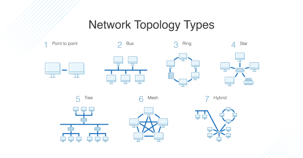
Topology
Topology describes how nodes and links fit together in a network configuration, frequently depicted in a diagram. Here are some common network topology types:
A network consists of nodes, links between nodes, and protocols that govern data manual between nodes.
At whatsoever calibration and complexity networks get to, y'all will sympathise what's happening in all computer networks by learning the OSI model and 7 layers of networking.
What is the OSI Model?
The OSI model consists of 7 layers of networking.
First, what'southward a layer?

Ooo, lair.
No, a layer - not a lair. Here at that place are no dragons.
A layer is a way of categorizing and grouping functionality and beliefs on and of a network.
In the OSI model, layers are organized from the about tangible and most concrete, to less tangible and less physical merely closer to the end user.
Each layer abstracts lower level functionality away until by the time you get to the highest layer. All the details and inner workings of all the other layers are hidden from the finish user.
How to call back all the names of the layers? Easy.
- Please | Physical Layer
- Practice | Data Link Layer
- Non | Network Layer
- Tell (the) | Transport Layer
- Secret | Session Layer
- Password (to) | Presentation Layer
- Anyone | Application Layer
Keep in heed that while certain technologies, like protocols, may logically "vest to" ane layer more than another, not all technologies fit neatly into a single layer in the OSI model. For instance, Ethernet, 802.11 (Wifi) and the Address Resolution Protocol (ARP) procedure operate on >1 layer.
The OSI is a model and a tool, not a set of rules.
OSI Layer i
Layer ane is the concrete layer. There's a lot of technology in Layer 1 - everything from physical network devices, cabling, to how the cables hook up to the devices. Plus if we don't need cables, what the signal type and manual methods are (for example, wireless broadband).
Instead of listing every type of applied science in Layer 1, I've created broader categories for these technologies. I encourage readers to learn more almost each of these categories:
- Nodes (devices) and networking hardware components. Devices include hubs, repeaters, routers, computers, printers, and then on. Hardware components that alive inside of these devices include antennas, amplifiers, Network Interface Cards (NICs), and more.
- Device interface mechanics. How and where does a cable connect to a device (cable connector and device socket)? What is the size and shape of the connector, and how many pins does it take? What dictates when a pivot is active or inactive?
- Functional and procedural logic. What is the office of each pin in the connector - ship or receive? What procedural logic dictates the sequence of events so a node tin can kickoff to communicate with another node on Layer ii?
- Cabling protocols and specifications. Ethernet (CAT), USB, Digital Subscriber Line (DSL), and more. Specifications include maximum cable length, modulation techniques, radio specifications, line coding, and $.25 synchronization (more on that beneath).
- Cable types. Options include shielded or unshielded twisted pair, untwisted pair, coaxial and so on. Learn more about cablevision types hither.
- Betoken blazon. Baseband is a unmarried bit stream at a time, like a railway runway - 1-way simply. Broadband consists of multiple bit streams at the aforementioned time, like a bi-directional highway.
- Signal transmission method (may exist wired or cablevision-free). Options include electrical (Ethernet), light (optical networks, fiber optics), radio waves (802.eleven WiFi, a/b/thou/n/ac/ax variants or Bluetooth). If cable-complimentary, then also consider frequency: 2.5 GHz vs. v GHz. If it's cabled, consider voltage. If cabled and Ethernet, likewise consider networking standards like 100BASE-T and related standards.
The data unit on Layer 1 is the fleck.
A bit the smallest unit of transmittable digital information. Bits are binary, and so either a 0 or a 1. Bytes, consisting of 8 $.25, are used to represent single characters, like a alphabetic character, numeral, or symbol.
$.25 are sent to and from hardware devices in accordance with the supported information rate (transmission rate, in number of $.25 per second or millisecond) and are synchronized so the number of bits sent and received per unit of time remains consistent (this is called bit synchronization). The way bits are transmitted depends on the signal transmission method.
Nodes can send, receive, or send and receive bits. If they can only practise ane, then the node uses a simplex mode. If they can practise both, so the node uses a duplex mode. If a node can ship and receive at the same time, it's total-duplex – if not, it's simply half-duplex.
The original Ethernet was one-half-duplex. Full-duplex Ethernet is an option now, given the correct equipment.
How to Troubleshoot OSI Layer 1 Problems
Here are some Layer 1 problems to watch out for:
- Defunct cables, for example damaged wires or broken connectors
- Broken hardware network devices, for example damaged circuits
- Stuff being unplugged (...we've all been there)
If there are issues in Layer 1, anything beyond Layer 1 volition non function properly.
TL;DR
Layer 1 contains the infrastructure that makes communication on networks possible.
It defines the electrical, mechanical, procedural, and functional specifications for activating, maintaining, and deactivating physical links between network devices. - Source
Fun fact: deep-sea communications cables transmit data effectually the world. This map will blow your listen: https://www.submarinecablemap.com/
And because you lot made it this far, here'due south a koala:

OSI Layer 2
Layer 2 is the data link layer. Layer two defines how data is formatted for manual, how much data can period between nodes, for how long, and what to do when errors are detected in this flow.
In more official tech terms:
- Line discipline. Who should talk for how long? How long should nodes be able to transit information for?
- Flow control. How much data should be transmitted?
- Error control - detection and correction. All data transmission methods take potential for errors, from electrical spikes to muddy connectors. In one case Layer ii technologies tell network administrators about an issue on Layer two or Layer 1, the system administrator can correct for those errors on subsequent layers. Layer ii is by and large concerned with error detection, not error correction. (Source)
There are 2 distinct sublayers within Layer ii:
- Media Admission Control (MAC): the MAC sublayer handles the assignment of a hardware identification number, called a MAC accost, that uniquely identifies each device on a network. No 2 devices should take the same MAC accost. The MAC address is assigned at the point of manufacturing. It is automatically recognized by well-nigh networks. MAC addresses live on Network Interface Cards (NICs). Switches keep track of all MAC addresses on a network. Learn more than about MAC addresses on PC Mag and in this article. Learn more about network switches here.
- Logical Link Control (LLC): the LLC sublayer handles framing addressing and flow control. The speed depends on the link between nodes, for case Ethernet or Wifi.
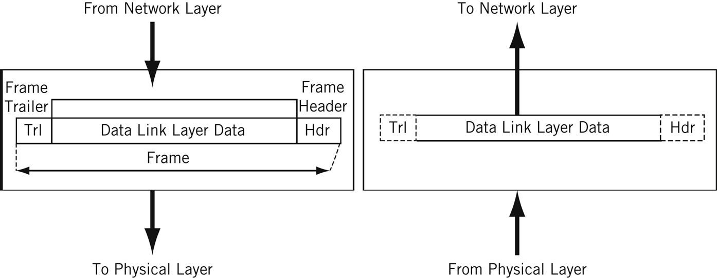
The data unit on Layer ii is a frame.
Each frame contains a frame header, body, and a frame trailer:
- Header: typically includes MAC addresses for the source and destination nodes.
- Body: consists of the bits being transmitted.
- Trailer: includes fault detection data. When errors are detected, and depending on the implementation or configuration of a network or protocol, frames may be discarded or the fault may be reported up to higher layers for farther error correction. Examples of fault detection mechanisms: Cyclic Back-up Check (CRC) and Frame Check Sequence (FCS). Learn more about mistake detection techniques here.
Typically there is a maximum frame size limit, called an Maximum Transmission Unit, MTU. Jumbo frames exceed the standard MTU, learn more nearly jumbo frames here.
How to Troubleshoot OSI Layer 2 Bug
Hither are some Layer 2 bug to watch out for:
- All the problems that tin occur on Layer 1
- Unsuccessful connections (sessions) between two nodes
- Sessions that are successfully established but intermittently fail
- Frame collisions
TL;DR
The Information Link Layer allows nodes to communicate with each other within a local area network. The foundations of line discipline, flow control, and mistake control are established in this layer.
OSI Layer 3
Layer 3 is the network layer. This is where we send information betwixt and across networks through the utilise of routers. Instead of simply node-to-node communication, nosotros can at present practise network-to-network advice.
Routers are the workhorse of Layer 3 - we couldn't accept Layer 3 without them. They move data packets beyond multiple networks.
Not only do they connect to Cyberspace Service Providers (ISPs) to provide access to the Internet, they also keep track of what'due south on its network (remember that switches keep track of all MAC addresses on a network), what other networks it's continued to, and the unlike paths for routing data packets across these networks.
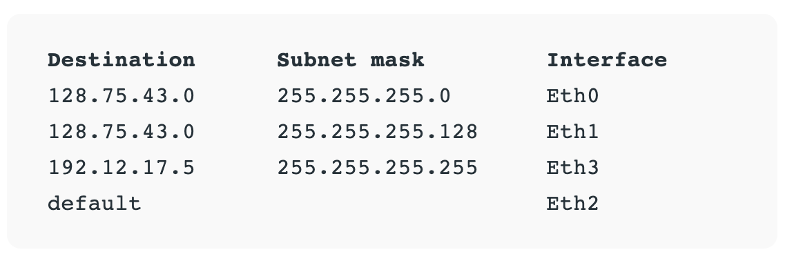
Routers store all of this addressing and routing information in routing tables.
Here'southward a unproblematic example of a routing table:
The data unit on Layer iii is the data bundle. Typically, each data packet contains a frame plus an IP address data wrapper. In other words, frames are encapsulated past Layer iii addressing data.
The data being transmitted in a package is also sometimes called the payload. While each packet has everything information technology needs to get to its destination, whether or not it makes it there is another story.
Layer 3 transmissions are connectionless, or best effort - they don't do anything but send the traffic where it's supposed to go. More on data transport protocols on Layer 4.
Once a node is connected to the Internet, it is assigned an Internet Protocol (IP) address, which looks either like 172.16. 254.i (IPv4 address convention) or similar 2001:0db8:85a3:0000:0000:8a2e:0370:7334 (IPv6 accost convention). Routers use IP addresses in their routing tables.
IP addresses are associated with the physical node's MAC accost via the Accost Resolution Protocol (ARP), which resolves MAC addresses with the node's corresponding IP accost.
ARP is conventionally considered role of Layer ii, but since IP addresses don't exist until Layer 3, it's too function of Layer 3.
How to Troubleshoot OSI Layer 3 Issues
Hither are some Layer 3 problems to watch out for:
- All the problems that can crop up on previous layers :)
- Faulty or not-functional router or other node
- IP accost is incorrectly configured
Many answers to Layer 3 questions volition crave the use of command-line tools like ping, trace, testify ip route, or bear witness ip protocols. Acquire more about troubleshooting on layer 1-iii here.
TL;DR
The Network Layer allows nodes to connect to the Internet and send information across dissimilar networks.
OSI Layer 4
Layer iv is the transport layer. This where we dive into the nitty gritty specifics of the connection betwixt two nodes and how information is transmitted between them. It builds on the functions of Layer ii - line discipline, flow control, and error control.
This layer is besides responsible for data packet segmentation, or how data packets are broken upward and sent over the network.
Unlike the previous layer, Layer 4 also has an understanding of the whole bulletin, not just the contents of each individual data bundle. With this understanding, Layer 4 is able to manage network congestion past not sending all the packets at once.
The data units of Layer 4 go past a few names. For TCP, the information unit is a packet. For UDP, a packet is referred to as a datagram. I'll just use the term data parcel here for the sake of simplicity.
Transmission Command Protocol (TCP) and User Datagram Protocol (UDP) are two of the about well-known protocols in Layer 4.
TCP, a connection-oriented protocol, prioritizes information quality over speed.
TCP explicitly establishes a connection with the destination node and requires a handshake betwixt the source and destination nodes when information is transmitted. The handshake confirms that data was received. If the destination node does not receive all of the information, TCP volition inquire for a retry.
TCP as well ensures that packets are delivered or reassembled in the correct order. Learn more than about TCP here.
UDP, a connectionless protocol, prioritizes speed over data quality. UDP does not require a handshake, which is why it's called connectionless.
Because UDP doesn't have to wait for this acknowledgement, it can transport information at a faster rate, but not all of the data may be successfully transmitted and we'd never know.
If information is dissever up into multiple datagrams, unless those datagrams comprise a sequence number, UDP does not ensure that packets are reassembled in the correct order. Acquire more about UDP here.
TCP and UDP both send information to specific ports on a network device, which has an IP address. The combination of the IP address and the port number is called a socket.
Learn more nearly sockets here.
Larn more about the differences and similarities between these 2 protocols here.
How to Troubleshoot OSI Layer iv Problems
Hither are some Layer 4 problems to watch out for:
- All the problems that can crop up on previous layers :)
- Blocked ports - cheque your Access Command Lists (ACL) & firewalls
- Quality of Service (QoS) settings. QoS is a characteristic of routers/switches that can prioritize traffic, and they can really muck things up. Learn more about QoS here.
TL;DR
The Transport Layer provides end-to-end transmission of a message by segmenting a message into multiple data packets; the layer supports connection-oriented and connectionless communication.
OSI Layer 5
Layer 5 is the session layer. This layer establishes, maintains, and terminates sessions.
A session is a mutually agreed upon connexion that is established betwixt two network applications. Not two nodes! Nope, we've moved on from nodes. They were then Layer iv.
Just kidding, nosotros nonetheless have nodes, but Layer 5 doesn't need to retain the concept of a node because that's been abstracted out (taken care of) by previous layers.
So a session is a connexion that is established betwixt ii specific end-user applications. There are two important concepts to consider hither:
- Client and server model: the awarding requesting the data is called the client, and the awarding that has the requested information is called the server.
- Request and response model: while a session is being established and during a session, there is a abiding back-and-forth of requests for information and responses containing that information or "hey, I don't have what you're requesting."
Sessions may be open for a very short amount of time or a long amount of time. They may fail sometimes, too.
Depending on the protocol in question, various failure resolution processes may kicking in. Depending on the applications/protocols/hardware in use, sessions may support simplex, half-duplex, or total-duplex modes.
Examples of protocols on Layer 5 include Network Basic Input Output System (NetBIOS) and Remote Procedure Telephone call Protocol (RPC), and many others.
From here on out (layer 5 and upwardly), networks are focused on means of making connections to finish-user applications and displaying data to the user.
How to Troubleshoot OSI Layer 5 Problems
Hither are some Layer 5 issues to watch out for:
- Servers are unavailable
- Servers are incorrectly configured, for example Apache or PHP configs
- Session failure - disconnect, timeout, and then on.
TL;DR
The Session Layer initiates, maintains, and terminates connections betwixt ii end-user applications. Information technology responds to requests from the presentation layer and issues requests to the transport layer.
OSI Layer vi
Layer vi is the presentation layer. This layer is responsible for data formatting, such as character encoding and conversions, and data encryption.
The operating organisation that hosts the cease-user awarding is typically involved in Layer 6 processes. This functionality is not always implemented in a network protocol.
Layer six makes sure that finish-user applications operating on Layer vii tin successfully consume data and, of grade, eventually display it.
There are three data formatting methods to be aware of:
- American Standard Lawmaking for Information Interchange (ASCII): this 7-scrap encoding technique is the nigh widely used standard for graphic symbol encoding. One superset is ISO-8859-ane, which provides most of the characters necessary for languages spoken in Western Europe.
- Extended Binary-Coded Decimal Interchange Code (EBDCIC): designed by IBM for mainframe usage. This encoding is incompatible with other grapheme encoding methods.
- Unicode: grapheme encodings tin can be done with 32-, sixteen-, or 8-bit characters and attempts to conform every known, written alphabet.
Acquire more nearly character encoding methods in this article, and also here.
Encryption: SSL or TLS encryption protocols live on Layer 6. These encryption protocols aid ensure that transmitted information is less vulnerable to malicious actors by providing authentication and information encryption for nodes operating on a network. TLS is the successor to SSL.
How to Troubleshoot OSI Layer 6 Problems
Hither are some Layer half dozen bug to sentinel out for:
- Non-existent or corrupted drivers
- Incorrect Os user access level
TL;DR
The Presentation Layer formats and encrypts data.
OSI Layer vii
Layer 7 is the application layer.
True to its name, this is the layer that is ultimately responsible for supporting services used by end-user applications. Applications include software programs that are installed on the operating system, like Internet browsers (for example, Firefox) or give-and-take processing programs (for instance, Microsoft Discussion).
Applications can perform specialized network functions under the hood and require specialized services that fall under the umbrella of Layer 7.
Electronic mail programs, for case, are specifically created to run over a network and utilize networking functionality, such as electronic mail protocols, which fall under Layer vii.
Applications will besides control terminate-user interaction, such as security checks (for example, MFA), identification of two participants, initiation of an exchange of data, and so on.
Protocols that operate on this level include File Transfer Protocol (FTP), Secure Shell (SSH), Simple Mail Transfer Protocol (SMTP), Cyberspace Message Access Protocol (IMAP), Domain Name Service (DNS), and Hypertext Transfer Protocol (HTTP).
While each of these protocols serve different functions and operate differently, on a high level they all facilitate the communication of information. (Source)
How to Troubleshoot OSI Layer 7 Problems
Here are some Layer 7 bug to lookout out for:
- All issues on previous layers
- Incorrectly configured software applications
- User mistake (... nosotros've all been there)
TL;DR
The Awarding Layer owns the services and functions that stop-user applications need to piece of work. Information technology does not include the applications themselves.
Determination
Our Layer 1 koala is all grown upward.

Learning check - tin can you apply makeup to a koala?
Don't accept a koala?
Well - respond these questions instead. Information technology'southward the next best thing, I hope.
- What is the OSI model?
- What are each of the layers?
- How could I utilise this information to troubleshoot networking issues?
Congratulations - you've taken i footstep further to understanding the glorious entity nosotros telephone call the Internet.
Learning Resources
Many, very smart people accept written unabridged books nigh the OSI model or entire books almost specific layers. I encourage readers to check out any O'Reilly-published books nearly the subject or about network applied science in general.
Here are some resources I used when writing this article:
- The Illustrated Network, 2nd Edition
- Protocol Data Unit (PDU): https://www.geeksforgeeks.org/difference-between-segments-packets-and-frames/
- Troubleshooting Along the OSI Model: https://www.pearsonitcertification.com/articles/article.aspx?p=1730891
- The OSI Model Demystified: https://www.youtube.com/picket?v=HEEnLZV2wGI
- OSI Model for Dummies: https://www.dummies.com/programming/networking/layers-in-the-osi-model-of-a-computer-network/
About Me
Chloe Tucker is an artist and computer science enthusiast based in Portland, Oregon. As a sometime educator, she's continuously searching for the intersection of learning and pedagogy, or engineering science and art. Reach out to her on Twitter @_chloetucker and check out her website at chloe.dev.
Learn to code for free. freeCodeCamp's open source curriculum has helped more than xl,000 people get jobs as developers. Go started

What Seven-layer Model Is Often Used To Describe Networking Technologies And Services?,
Source: https://www.freecodecamp.org/news/osi-model-networking-layers-explained-in-plain-english/
Posted by: ramirezdecterral52.blogspot.com
0 Response to "What Seven-layer Model Is Often Used To Describe Networking Technologies And Services?"
Post a Comment